- Flex PCB Blog
- PCB Assembly Blog
- FPC Research Blog
- Preparation of FPC based on ultrasonic spraying method_4_Experimental Results
- Preparation of FPC based on ultrasonic spraying method_3_Experimental Procedure
- Preparation of FPC based on ultrasonic spraying method_2_Experimental Platform and Principle
- Preparation of FPC based on ultrasonic spraying method_1_abstract
- Research on Layout Design Method of Ultra-thin FPC_4_Analysis of Layout Design Methods
- Research on Layout Design Method of Ultra-thin FPC_3_Analysis of Layout Design Methods
- Research on Layout Design Method of Ultra-thin FPC_2_Analysis of Layout Design Methods
- Research on Layout Design Method of Ultra-thin FPC_1_introduction
- Research progress on polyimide FPC_2_the field of FPC
- Research progress on polyimide FPC_1_Introduction
- Analysis of Vibration Characteristics of FPCBs _4_Summary
- Analysis of Vibration Characteristics of FPCBs _3_Finite Element Analysis
- Analysis of Vibration Characteristics of FPCBs _2_Theory of Vibration Analysis
- Analysis of Vibration Characteristics of FPCBs Under Random Vibration_1_Introduction
- Design Methods for FPCBs_5_Practical Application
- Design Methods for FPCBs_4_Electrical Circuit Design and Examples
- Design Methods for FPCBs_3_Structure Design Method and Examples
- Design Methods for FPCBs_2_Component Selection Methodology and Examples.
- Research on Design Methods for FPCBs
- Application of MPW technique for FPCBs _4_Summary
- Application of MPW technique for FPCBs_3_Experimental results
- Application of MPW technique for FPCBs_2_Experimental setup
- Application of MPW technique for FPCBs_1_Principle of MPW
- Application of FPCB in PC motherboards_4_ Results and discussion
- Application of FPCB in PC motherboards_3_ Numerical analysis
- Application of FPCB in PC_2_ Experimentation
- Application of FPCB in PC motherboards
- A Bus Planning Algorithm for FPC Design _4_Experimental result
- A Bus Planning Algorithm for FPC Design _3_Proposed Algorithm
- A Bus Planning Algorithm for FPC Design _2_Preliminaries
- A Bus Planning Algorithm for FPC Design _1_Introduction
Application of flexible printed circuit board (FPCB) in personal computer motherboards
Focusing on mechanical performance_3_ Numerical analysis
3. Numerical analysis
3.1. Simulation tools
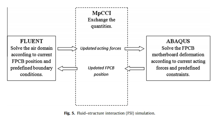
The FSI numerical analysis was performed using the fluid solver FLUENT 6.3.26 and structural solver ABAQUS/CAE 6.9, coupled online by MpCCI 3.1.0. Using the MpCCI, the quantities were exchanged from one solver to the other through association (neighborhood search) and interpolation. In the present study, the air flow is solved by FLUENT, and the subsequent deformation of FPCB motherboard is addressed by ABAQUS. The deformation information is then fed back to FLUENT, and this process completes one cycle of iteration, as shown in Fig. 5.
3.2. Modeling strategy
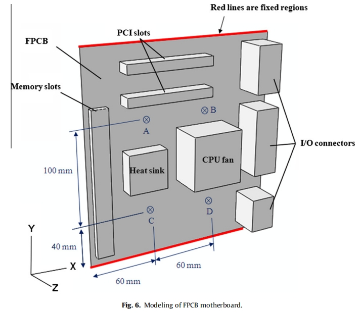
In ABAQUS, as shown in Fig. 6, the components of the FPCB motherboard are modeled as idealized simple blocks, which are rigidly attached to the motherboard with no consideration made for attachment flexibility. This simplified modeling technique is reliable, as demonstrated in the previous studies conducted by Pitarresi et al.As given in Table 1, the effective elastic modulus, density, and dimensions of the various components are specified according to the experimental prototype. The fully constrained boundary condition (Ux =Uy = Uz = URx = URy = URz = 0) is assigned to the fixed regions of the motherboard, where U and UR denote linear and rotational displacements, respectively. Gravity is defined in the negative y-direction. Points A, B, C, and D are the locations where the comparison between experimental measurements and numerical predictions are made. This structural model is meshed with 28,353 hexagonal elements.
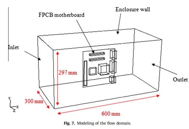
In FLUENT, the flow is assumed to be three dimensional, lami- nar, incompressible, and unsteady. The laminar model is well sui- ted for a fan-sucking wind tunnel, as investigated by Grimes and co-workers . As shown in Fig.7, the fluid model covers the entire test section of the wind tunnel and is meshed with 848,175 hexagonal grids. For the purpose of structured mesh assignment in fluid modeling, the fluid domain is appropriately split into a few smaller volumes. The motherboard stand holder is not modeled to reduce modeling complexity. In this model, the desired velocity is set at the velocity inlet boundary, and ambient condition is set at the pressure outlet boundary.
3.3. Case studies
The reliability of this FSI simulation technique was substantiated by comparing the predictions with experimental measurements. A few studies were conducted to investigate the deflection and stress induced in the FPCB motherboard under various conditions. First, the inlet velocities were manipulated at 1, 2, 3, 4, and 5 m/s, which are within the typical range found in electronic systems, to examine the effect of flow velocity on the motherboard. In addition, different fastening options were considered, as shown in Fig. 8. Due to the fact that the motherboard is commonly screw-fastened at several points in actual applications.
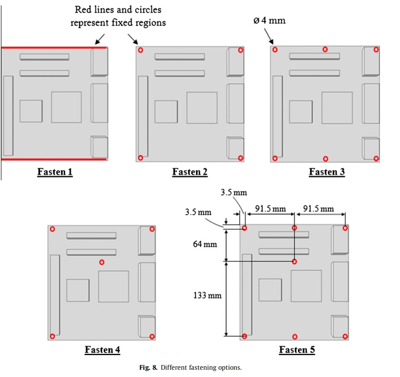
Fastens 2 and 3 were considered to discover the screw-fastening effects. Fastens 4 and 5 were also tested to evaluate the performance of the mounting when the motherboard was screwed at the middle. In addition, the different component layouts were anticipated to also have significant effects on the mechanical behavior of the FPCB motherboard. Hence, a few possibilities of the component layouts were also examined, as shown in Fig. 9. In these layouts, the locations of the I/O connectors were not altered because of the idea that they are normally placed at the downstream of the motherboard. These layout investigations can clarify some questions on a few outcomes, such as the different orientations of the long memory slots and different locations of the two bigger components (heat sink and CPU fan).
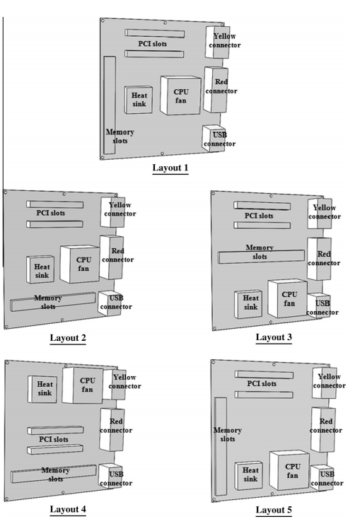
Fig.9. different compontent layout


